
If you’ve ever found yourself running out of digital pins on an Arduino project, you’re not alone. Whether you’re lighting up multiple LEDs, controlling a display, or working with any other components that demand numerous outputs, the limited number of pins on the Arduino can quickly become a challenge. That’s where shift registers come to the rescue.
The 74HC595 is one of the most popular and beginner-friendly shift registers available. It allows you to control eight outputs using just three pins on your Arduino (although in this example, we’ll be using four for added stability and clarity). Even better, you can daisy-chain multiple 74HC595 chips together, giving you virtually unlimited output expansion with minimal pin usage.
In this guide, we’ll walk through everything you need to know to get started with the 74HC595 from connecting the hardware to writing your first bit of code to control it. Whether you’re new to electronics or just looking to expand your Arduino’s capabilities, this is a great project to learn from.
Getting Started: Connecting the 74HC595 to Your Arduino
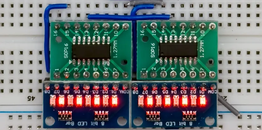
Let’s begin by connecting the 74HC595 shift register to the Arduino. For this example, I’m using SMD (Surface-Mount Device) versions of the 74HC595 that I had left over from a previous project. Because SMD components aren’t breadboard-friendly by default, I’ve soldered them onto SMD-to-DIP adapter boards, allowing me to easily use them with jumper wires and a breadboard just like the standard through-hole version of the chip.
This setup is perfectly fine for prototyping, and functionally it behaves exactly the same as any other version of the 74HC595. With the physical setup ready, we can move on to making the necessary connections to the Arduino. This will form the foundation for controlling multiple outputs with just a few data lines something that can make your future projects much cleaner and more efficient.
To control multiple outputs, we’ll be using two 74HC595 shift registers daisy-chained together. This means the serial output (Q7′) of the first chip connects directly to the serial input (SER) of the second chip, allowing data to be shifted from the Arduino through both chips in sequence. With this setup, we can control 16 output pins using just four Arduino pins.
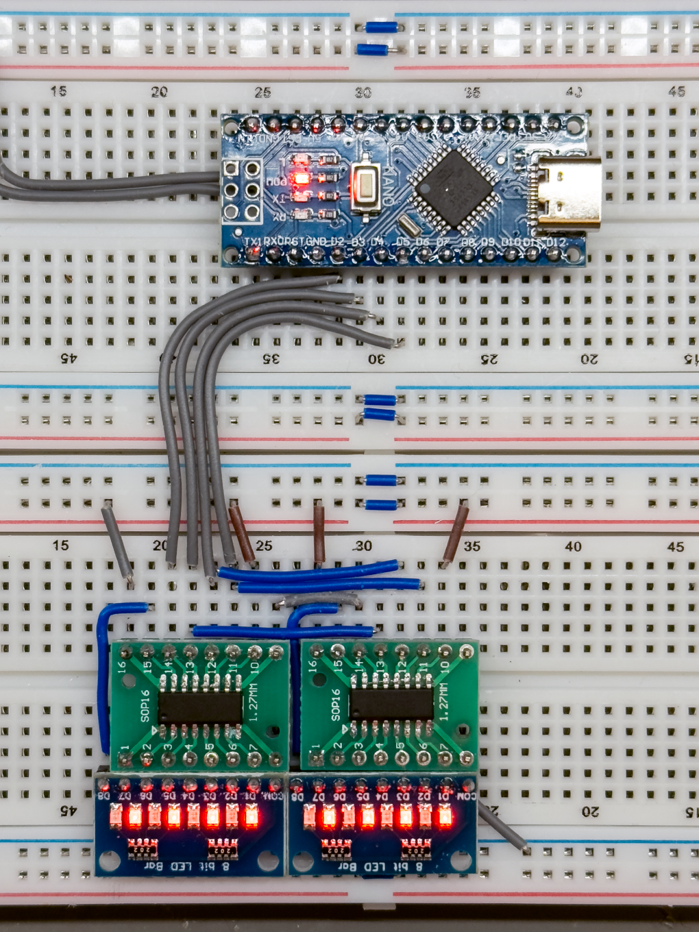
In this example, the Arduino uses the following pins:
DATA_PIN(Pin 2): Sends serial data to the shift registers.CLOCK_PIN(Pin 5): Connected to SHCP, pulses to shift each bit into the registers.LATCH_PIN(Pin 4): Connected to STCP, latches the shifted data to the output pins.OUTPUT_ENABLE_PIN(Pin 3): Connected to OE, enables or disables the outputs. This is typically kept LOW in software so the outputs remain active.
Wiring Overview
Start by connecting the first 74HC595 to the Arduino using the control pins listed above. The SER (Serial Data Input) pin of the first chip should be connected to DATA_PIN. Then, daisy-chain the chips by connecting Q7′ (serial data out) of Chip 1 to SER of Chip 2. This allows the second chip to receive the next 8 bits of data automatically as bits are shifted through.
Next, tie the SHCP (Shift Clock) and STCP (Latch Clock) pins of both chips together, and connect them to the CLOCK_PIN and LATCH_PIN on the Arduino. This ensures both chips shift and latch data simultaneously. Also connect both OE (Output Enable) pins together and wire them to OUTPUT_ENABLE_PIN. In your sketch, you’ll want to keep this pin LOW to activate the outputs.
Finally, make sure to connect VCC and GND to both chips to power them properly. Once everything is wired up, the two 74HC595s will function as a single 16-bit shift register. When you shift out 16 bits of data, the first 8 bits will go to the second chip, and the remaining 8 will stay in the first chip so the second chip actually controls outputs Q0–Q7, and the first chip controls Q8–Q15 in your sequence.
74HC595 to Arduino Wiring Table
| 74HC595 Pin Name | Chip #1 Connection | Chip #2 Connection | Arduino Pin | Notes |
|---|---|---|---|---|
| VCC | +5V | +5V | Power supply | |
| GND | GND | GND | Ground | |
| SER (DS) | From Arduino DATA_PIN | From Q7′ of Chip #1 | Pin 2 (DATA_PIN) | Serial data input |
| SHCP (Shift Clock) | Connected together | Connected together | Pin 5 (CLOCK_PIN) | Clock to shift bits into the register |
| STCP (Latch Clock) | Connected together | Connected together | Pin 4 (LATCH_PIN) | Latch to transfer data to output pins |
| OE | Connected together | Connected together | Pin 3 (OUTPUT_ENABLE_PIN) | Output Enable (LOW = outputs active) |
| MR | +5V (or pull-up resistor) | +5V (or pull-up resistor) | Master Reset (active LOW), tie HIGH to disable reset | |
| Q7′ (Serial Out) | Connect to SER of Chip #2 | Used to daisy-chain to the next chip | ||
| QA – QH (Outputs) | Connect to LEDs or other load | Connect to LEDs or other load | Output pins controlled via shifting/latching |
Toggling an Alternating LED Pattern
Let’s start with a simple example to demonstrate how to send data to the two chained 74HC595 shift registers. In this sketch, we’ll turn on every other LED in an alternating pattern, switching back and forth every second. Since each shift register controls 8 outputs, and we’re using two, we’ll be lighting up 16 LEDs total in a repeating “on-off-on-off” style.
This is a great way to confirm your wiring is correct and that both chips are receiving and responding to the data properly.
Code Breakdown
// Define control pins for the shift register
const uint8_t DATA_PIN   = 2;   // Data pin (DS)
const uint8_t CLOCK_PIN  = 5;   // Clock pin (SHCP)
const uint8_t LATCH_PIN  = 4;   // Latch pin (STCP)
const uint8_t OUTPUT_ENABLE_PIN = 3; // Output Enable (OE), active LOW
These constants define which Arduino pins are connected to the shift register’s control lines. You can change these if your wiring is different.
// Control flag to toggle between patterns
bool FLAG = true;
This boolean flag helps us alternate between two LED patterns on each loop.
void setup() {
  // Configure pins as outputs
  pinMode(LATCH_PIN, OUTPUT);
  pinMode(CLOCK_PIN, OUTPUT);
  pinMode(DATA_PIN, OUTPUT);
  pinMode(OUTPUT_ENABLE_PIN, OUTPUT);

  // Enable outputs (OE is active LOW)
  digitalWrite(OUTPUT_ENABLE_PIN, LOW);
}
In setup(), we set all the control pins as outputs and enable the output pins by setting OE low.
void loop() {
  // Prepare to send data
  digitalWrite(LATCH_PIN, LOW);
We pull the latch pin LOW to tell the shift registers we’re about to send new data.
  // Choose data pattern based on FLAG and toggle FLAG
  byte data;
  if (FLAG) {
    data = 0b10101010;
    FLAG = false;
  } else {
    data = 0b01010101;
    FLAG = true;
  }
This code selects one of two alternating 8-bit patterns (binary 10101010 and 01010101), which will cause every other LED to light up. The FLAG toggles between them each cycle.
  // Shift the data out to two chained shift registers
  shiftOut(DATA_PIN, CLOCK_PIN, MSBFIRST, data);
  shiftOut(DATA_PIN, CLOCK_PIN, MSBFIRST, data);
We send two bytes of data, one for each shift register. Since both bytes are the same, both chips will show the same alternating LED pattern.
  // Latch the data to the output pins
  digitalWrite(LATCH_PIN, HIGH);
Once both bytes are sent, we set the latch pin HIGH to update the outputs with the new data.
  // Wait for a second
  delay(1000);
}
Finally, we add a 1-second delay before the next loop, giving time to see the LED pattern before it changes again.
This loop will continue to alternate the LED pattern every second, making it a perfect starting test for verifying your shift register setup. Both chips will light up their outputs in a checkerboard-like pattern, switching back and forth to show that data is flowing through the chain correctly.
Full Code: Alternating LED Pattern Using Two 74HC595 Shift Registers with Arduino
// Define control pins for the shift register
const uint8_t DATA_PIN   = 2;   // Data pin (DS)
const uint8_t CLOCK_PIN  = 5;   // Clock pin (SHCP)
const uint8_t LATCH_PIN  = 4;   // Latch pin (STCP)
const uint8_t OUTPUT_ENABLE_PIN = 3; // Output Enable (OE), active LOW

// Control flag to toggle between patterns
bool FLAG = true;

void setup() {
  // Configure pins as outputs
  pinMode(LATCH_PIN, OUTPUT);
  pinMode(CLOCK_PIN, OUTPUT);
  pinMode(DATA_PIN, OUTPUT);
  pinMode(OUTPUT_ENABLE_PIN, OUTPUT);

  // Enable outputs (OE is active LOW)
  digitalWrite(OUTPUT_ENABLE_PIN, LOW);
}

void loop() {
  // Prepare to send data
  digitalWrite(LATCH_PIN, LOW);

  // Choose data pattern based on FLAG and toggle FLAG
  byte data;
  if (FLAG) {
    data = 0b10101010;
    FLAG = false; // Flip flag for next time
  } else {
    data = 0b01010101;
    FLAG = true;
  }

  // Shift the data out to two chained shift registers
  shiftOut(DATA_PIN, CLOCK_PIN, MSBFIRST, data);
  shiftOut(DATA_PIN, CLOCK_PIN, MSBFIRST, data);

  // Latch the data to the output pins
  digitalWrite(LATCH_PIN, HIGH);

  // Wait for a second
  delay(1000);
}
Watch It in Action
Here’s a quick demonstration of the code in action. You’ll see the LEDs toggling in an alternating pattern across both shift registers, proving that data is being correctly shifted and latched through the chain.
Demo 2: Running Light with a Clock–Latch Jumper
In this second demo, we’re creating a simple but visually satisfying “running light” effect, where a single illuminated LED appears to move across all 16 outputs. This is a classic way to test shift register timing and visualize data flow.
For this to work, we’ve placed a jumper wire between the CLOCK and LATCH pins on the shift registers. This means every time we send a clock pulse, the data is not only shifted in but also immediately latched to the outputs. As a result, there’s no need to manually control the LATCH pin in software every bit update is instantly reflected on the LEDs.
This setup is ideal for creating effects where each individual bit should be visible as it arrives, such as LED chasers or binary counters.
Code Breakdown
// Define control pins for the shift register
const uint8_t DATA_PIN   = 2;   // Data pin (DS) – used to send bits into the shift register
const uint8_t CLOCK_PIN  = 5;   // Clock pin (SHCP) – toggled to shift bits into the register
const uint8_t LATCH_PIN  = 4;   // Latch pin (STCP) – not used directly here due to jumper
const uint8_t OUTPUT_ENABLE_PIN = 3; // Output Enable (OE) – active LOW, enables/disables output

const uint8_t NUM_LEDS    = 16;      // Number of output bits (or LEDs)
const uint16_t STEP_DELAY = 150;     // Delay between LED updates for effect
We define the necessary control pins, total number of bits to shift (16 LEDs), and a small delay to slow down the animation.
void pulseClock() {
  digitalWrite(CLOCK_PIN, HIGH);
  delayMicroseconds(5);
  digitalWrite(CLOCK_PIN, LOW);
  delayMicroseconds(5);
}
This function handles one full clock pulse, which shifts the current bit into the register. Because of the jumper, this also automatically latches the output.
void setup() {
  pinMode(DATA_PIN, OUTPUT);
  pinMode(CLOCK_PIN, OUTPUT);
  pinMode(OUTPUT_ENABLE_PIN, OUTPUT);

  digitalWrite(OUTPUT_ENABLE_PIN, LOW); // Enable outputs
}
We initialize the data, clock, and output enable pins, and keep OE LOW to turn the outputs on.
void loop() {
  // Send a HIGH bit for the first LED
  digitalWrite(DATA_PIN, HIGH);
  pulseClock();
  delay(STEP_DELAY);

  // Send LOW bits for the rest
  digitalWrite(DATA_PIN, LOW);
  for (uint8_t i = 1; i < NUM_LEDS; i++) {
    pulseClock();
    delay(STEP_DELAY);
  }
}
- The loop starts by sending one HIGH bit, which lights up the first LED.
- It then shifts in 15 LOW bits, pushing the HIGH bit across the chain one position at a time.
- Because each bit is latched instantly, we get a visible moving LED effect that travels from the first output to the last.
Full Code: Running Light with Clock–Latch Jumper
/*******************************************************
 * FOR THIS DEMO, WE HAVE PLACED A JUMPER BETWEEN CLOCK AND LATCH
 *******************************************************/

// Define control pins for the shift register
const uint8_t DATA_PIN   = 2;   // Data pin (DS) – used to send bits into the shift register
const uint8_t CLOCK_PIN  = 5;   // Clock pin (SHCP) – toggled to shift bits into the register
const uint8_t LATCH_PIN  = 4;   // Latch pin (STCP) – not used directly here due to jumper
const uint8_t OUTPUT_ENABLE_PIN = 3; // Output Enable (OE) – active LOW, enables/disables output

// Number of LEDs (or bits) the shift register is controlling
const uint8_t NUM_LEDS    = 16;

// Time delay between each LED activation (used for visual effect)
const uint16_t STEP_DELAY = 150;

// Function to pulse the CLOCK pin: HIGH then LOW
void pulseClock() {
  digitalWrite(CLOCK_PIN, HIGH);     // Rising edge shifts in the bit on DATA
  delayMicroseconds(5);              // Short delay to ensure the clock is registered
  digitalWrite(CLOCK_PIN, LOW);      // Falling edge prepares for the next bit
  delayMicroseconds(5);              // Short delay before next operation
}

void setup() {
  // Set all control pins as outputs
  pinMode(DATA_PIN, OUTPUT);
  pinMode(CLOCK_PIN, OUTPUT);
  pinMode(OUTPUT_ENABLE_PIN, OUTPUT);

  // Enable outputs on the 74HCT595 (LOW = enabled)
  digitalWrite(OUTPUT_ENABLE_PIN, LOW);
}

void loop() {
  // Light the first LED by setting the first bit HIGH
  digitalWrite(DATA_PIN, HIGH);  // Send a HIGH bit
  pulseClock();                  // Push the HIGH bit into the shift register
  delay(STEP_DELAY);            // Wait for visual effect

  // Turn DATA LOW for remaining bits (so they are OFF)
  digitalWrite(DATA_PIN, LOW);

  // Shift in remaining LOW bits (all other LEDs OFF)
  for (uint8_t i = 1; i < NUM_LEDS; i++) {
    pulseClock();               // Push LOW into shift register
    delay(STEP_DELAY);         // Delay to maintain the "moving light" effect
  }
}
Watch It in Action
Here’s a quick video showing the LED “chase” pattern across all 16 outputs. You’ll notice how each light appears one by one thanks to the immediate latching via the jumper.
Final Demo: Knight Rider–Style LED Scanner with Manual Latching
For our final demo, we’re recreating the classic Knight Rider-style LED scanner effect, where a glowing block of lights smoothly sweeps back and forth just like KITT’s iconic red sensor. This time, we’ve removed the jumper between the CLOCK and LATCH pins, giving us precise manual control over when the outputs update.
This setup ensures that data is shifted in completely before it’s displayed, resulting in clean, flicker-free transitions. We’re also lighting up a group of LEDs (a “light block”) rather than just one at a time, making the animation appear more fluid and dramatic perfect for replicating the sci-fi vibe of a scanning eye or bar graph animation.
Code Breakdown
const uint8_t DATA_PIN   = 2;
const uint8_t CLOCK_PIN  = 5;
const uint8_t LATCH_PIN  = 4;
const uint8_t OUTPUT_ENABLE_PIN = 3;
These define the Arduino pins connected to the shift registers. We’re using the LATCH pin manually in this demo to control exactly when the outputs update.
const uint8_t NUM_LEDS = 16;
const uint8_t LEDS_ILLUMINATED = 3;
We’re controlling 16 outputs and lighting up 3 adjacent LEDs at a time to form the scanning block.
int ledPos = 0;
int direction = 1;
These track the current position of the LED block and which direction it’s moving left or right.
setup() Function
void setup() {
  pinMode(LATCH_PIN, OUTPUT);
  pinMode(CLOCK_PIN, OUTPUT);
  pinMode(DATA_PIN, OUTPUT);
  pinMode(OUTPUT_ENABLE_PIN, OUTPUT);

  digitalWrite(OUTPUT_ENABLE_PIN, LOW); // Enable outputs
}
Standard setup configuring pins and enabling output from the 74HC595s.
loop() Function
uint16_t pattern = 0;
for (int i = 0; i < LEDS_ILLUMINATED; i++) {
  int pos = ledPos + i;
  if (pos < NUM_LEDS) {
    pattern |= (1 << pos);
  }
}
We generate a 16-bit binary pattern where 3 bits in a row are set HIGH, starting from the current position (ledPos). This forms the “light block.”
byte highByte = (pattern >> 8) & 0xFF;
byte lowByte = pattern & 0xFF;
We split the pattern into two bytes one for each shift register.
digitalWrite(LATCH_PIN, LOW);
shiftOut(DATA_PIN, CLOCK_PIN, MSBFIRST, highByte);
shiftOut(DATA_PIN, CLOCK_PIN, MSBFIRST, lowByte);
digitalWrite(LATCH_PIN, HIGH);
This is where the manual latching happens. We only update the outputs after both bytes have been shifted in, which keeps the display glitch-free.
ledPos += direction;
if (ledPos <= 0 || ledPos >= (NUM_LEDS - LEDS_ILLUMINATED)) {
  direction = -direction;
}
The block bounces back when it reaches either end of the row of LEDs.
Full Code: Knight Rider–Style LED Scanner
/*******************************************************
 * FOR THIS DEMO, WE HAVE REMOVED THE JUMPER BETWEEN CLOCK AND LATCH
 *******************************************************/

// Shift register control pins
const uint8_t DATA_PIN   = 2;
const uint8_t CLOCK_PIN  = 5;
const uint8_t LATCH_PIN  = 4;
const uint8_t OUTPUT_ENABLE_PIN = 3;

// Configuration variables
const uint8_t NUM_LEDS = 16;        // Total number of LEDs
const uint8_t LEDS_ILLUMINATED = 3; // Number of adjacent LEDs to illuminate

int ledPos = 0;       // Starting position
int direction = 1;    // 1 = right, -1 = left

void setup() {
  pinMode(LATCH_PIN, OUTPUT);
  pinMode(CLOCK_PIN, OUTPUT);
  pinMode(DATA_PIN, OUTPUT);
  pinMode(OUTPUT_ENABLE_PIN, OUTPUT);

  digitalWrite(OUTPUT_ENABLE_PIN, LOW); // Enable output (active LOW)
}

void loop() {
  uint16_t pattern = 0;

  // Generate pattern with LEDS_ILLUMINATED bits set starting at ledPos
  for (int i = 0; i < LEDS_ILLUMINATED; i++) {
    int pos = ledPos + i;
    if (pos < NUM_LEDS) {
      pattern |= (1 << pos);
    }
  }

  // Extract bytes to send to the shift registers
  byte highByte = (pattern >> 8) & 0xFF;
  byte lowByte = pattern & 0xFF;

  // Send to shift registers
  digitalWrite(LATCH_PIN, LOW);
  shiftOut(DATA_PIN, CLOCK_PIN, MSBFIRST, highByte);
  shiftOut(DATA_PIN, CLOCK_PIN, MSBFIRST, lowByte);
  digitalWrite(LATCH_PIN, HIGH);

  // Update LED position
  ledPos += direction;

  // Reverse direction if we reach the ends
  if (ledPos <= 0 || ledPos >= (NUM_LEDS - LEDS_ILLUMINATED)) {
    direction = -direction;
  }

  delay(100); // Delay between frames
}
Watch It in Action
The video below shows the Knight Rider–inspired LED scanner effect in motion. A group of glowing LEDs moves smoothly from one side to the other and reverses giving that classic sci-fi sweeping look. This is a great way to show how effective clean latching can be when working with shift registers and timing.
Get the Code on GitHub
Want to try this yourself or explore the other demos? You can find all the example code from this project including the alternating pattern, running light, and Knight Rider-style scanner on my GitHub: